This blog post describes a simple crane yard simulation in AnyLogic. I developed this model in AnyLogic for demonstration purposes. I have already published a series of blog posts on simulation modeling in AnyLogic. Below is a list of some of them.
This post considers a storage yard for storage of processed parts. I will not consider the fill rate of the buffer itself. Nor will I model individual part tracking. That is, storage capacity is a blackbox and focus is on assessing throughput capabilities of the yard crane. This assumes a specified material flow matrix, describing in- and output rates to and from the buffer.
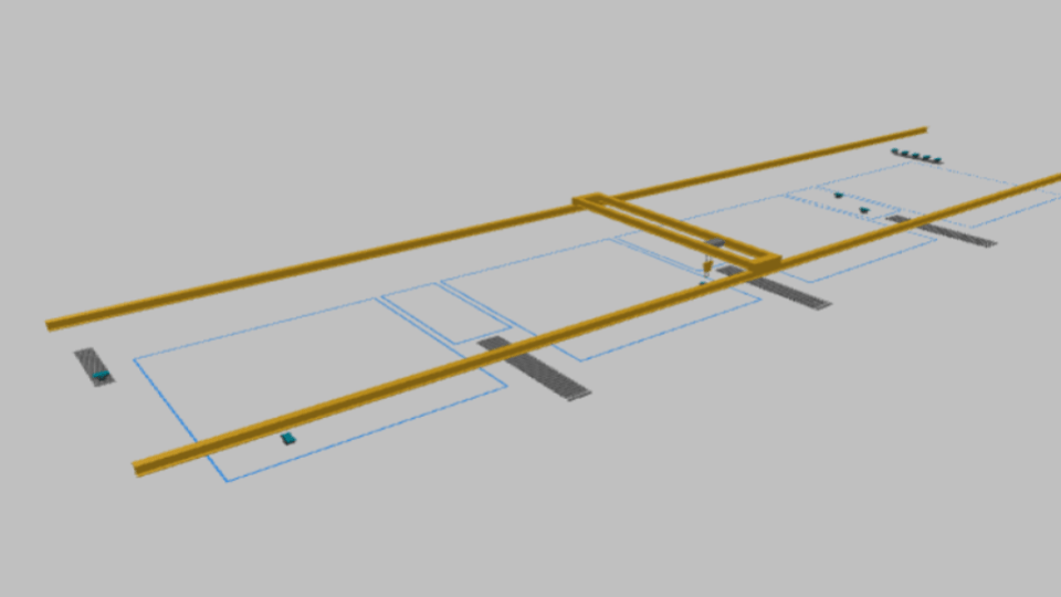
Overview of the crane yard simulation model
Below screenshot shows the main components of the AnyLogic crane yard simulation model. The storage yard has two inlet conveyors and three outlet conveyors. It is operated by a single horizontal yard crane.

It is a simple model that can be constructed in 1 hour. As stated in the introduction of this article individual part tracking is not part of the model. That means a part is put away in the buffer whereup it is destroyed. This is the production – putaway process in above logic block section. Retrievals from the yard are implemented as a separate process, utilizing the same yard crane. This is the retrieval – shipped process in above logic block section. The dwelling of parts in the yard is not modelled. Fill rates are not considered. The focus is on assessing maximum possible throughput of the yard crane.
Implementing storage slot and conveyor allocations
In this crane yard simulation model two allocation decisions have to be made:
- For a part that arrives on one of the inlet conveyors it has to be decided where in the yard the part should be stored
- For a part that has to be delivered to a downstream process, i.e. that has to be retrieved, it must be decided which conveyor the part should be placed on
Assigning parts to a storage location for putaway
Starting with the production – putaway process: This is implemented in below sequence of logic blocks.

A part is created by the source (agent of custom class part). This new part is located on one of the inlet conveyors using the logic blocks convey_a and convey_b. The probability of each inlet conveyor is 50%.
Next, a small custom function is called (allocation_01/allocation_02). This function simply decides which node (1 to 7), referred to as “bay”, the part should be stored in. It does so by setting the variables targetbay_01/targetbay_02. AnyLogic then seizes the crane and executes the transport to a random attractor within the specified node.
Retrieving parts from the yard and assigning them to a conveyor
For modeling part retrieval from the storage yard a sourcebay (source node), from which a part is to be retrieved, and a targetconveyor, on which the part is to be placed, have to be specified. To make this easier I placed these two variables inside the custom part agent class.

sourcebay and targetconveyor are also variables in the main model itself. However, they are merely used as temporary memory. On arrival of a new agent in the retrieval source the selection() function is called.

The selection function sets the temporary sourcebay and targetconveyor placeholders. The values of these variables are then written to the .sourcebay and .targetconveyor attributes of the newly arrived part agent (object instance). Below screenshot shows the selection function.

As you can see from above screenshot of the selection function code, retrieval locations are completely random. The target conveyor is then always the conveyor that is nearest to the crane.
Running the crane yard simulation in AnyLogic
AnyLogic visualizes its markup in 2D and 3D. Below screenshot shows a 2D snapshot of the simulation model during runtime.

After one hour of simulation 9 parts have been shipped (retrieved and delivered at the end of one of the exit conveyors) and 9 parts have been put away. Below is a screenshot of relevant blocks after one hour of simulation.

If I want to prioritize putaways over retrievals, or implement some other logic related to task prioritization, I could do that with JAVA functions, too.
Concluding remarks and related content
I presented a simple crane yard simulation model without individual part tracking. A model of this kind is appropriate for e.g. assessing equipment throughput. In this case the focus was on the throughput capacbilities of the horizontal yard crane.
If you are interested in simulation modeling and AnyLogic you might also find some of the following articles interesting:
- Link: Simulation-based capacity planning
- Link: Machine learning and discrete-event simulation
- Link: Parking lot simulator with simmer in R
- Link: Conveyor simulation in AnyLogic
- Link: Manufacturing simulation for plant design
- Link: Discrete-event simulation procedure model
- Link: Backlog simulation of FIFO production
- Link: Receival inspection simulation with simmer
- Link: Visual Components financial KPI simulation
- Link: Simmer in R for discrete-event simulation
- Link: Open-pit mine simulation for better planning
- Link: Simulation methods for SCM analysts
- Link: ProModel AutoCAD simulation edition
- Link: AGV simulation of part routings in AnyLogic
- Link: Conveyor simulation in AnyLogic

Data scientist focusing on simulation, optimization and modeling in R, SQL, VBA and Python


Leave a Reply